-
Linyin Business Plaza, No. 381 Taihua Street, Shijiazhuang City, Hebei Province, China
Linyin Business Plaza, No. 381 Taihua Street, Shijiazhuang City, Hebei Province, China
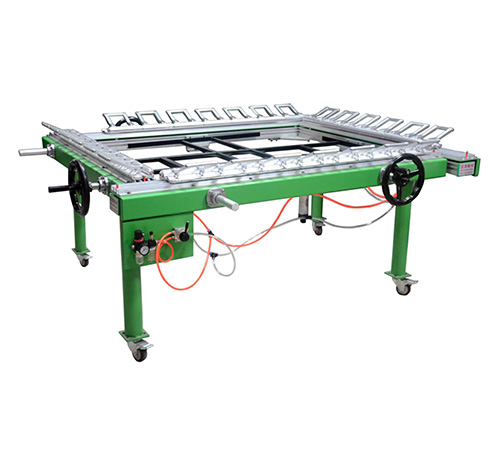
HUAJIN supply high quality Double rail double chuck net drawing machine which used in screen printing for small and larger printing object.
Tips:
1. During the use of the cylinder, be sure to add oil to the screw (spindle) every day to reduce friction.
|
Product Name |
Double rail double chuck net drawing machine |
|
Applicable temperature |
Between +5°C to +40°C |
|
Humidity |
It is required to be used normally in an environment where the corresponding humidity does not exceed 50% when the maximum temperature is +40°C |
|
Altitude |
Use at altitudes below 1000 meters. |
|
Transport storage |
This machine requires that the temperature of all equipped electrical equipment and structures be controlled at -7°C to 40°C during transportation and storage, and cannot exceed -15°C to 50°C for short-term transportation and storage within 24 hours. |
|
Maximum Stretch tension |
35N |
Stretching Machine Assembly Instructions
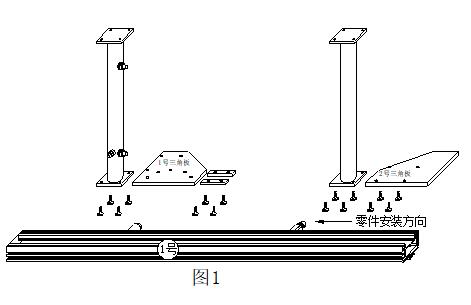
1. The first step, as shown in Figure 1: Place the back side of No. 1 main beam on the ground, and assemble the No. 1 machine foot (air tank machine foot, the machine foot is aligned with the end of the beam), No. 1 machine foot from right to left along the groove of the cross beam Install a backing block into each of the triangle plate and the two grooves along the beam; then install the No. 2 fixed foot along the groove of the beam from right to left (18CM is reserved from the right end of the machine foot to the end of the beam, and the distance between the No. 3 and No. 4 machine feet is the same) and No. 2 triangular plate.
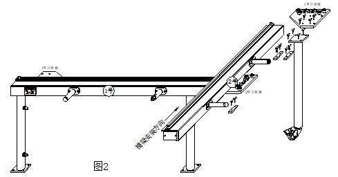
2. The second step, as shown in Figure 2: Flip the No. 1 beam, first along the groove of the No. 2 beam, install a block from right to left, and then install the No. 2 beam from left to right through the No. 2 triangular plate, along the Each of the two grooves on the right end of the beam is installed with a block, and then the No. 3 machine foot and the No. 3 triangle plate;
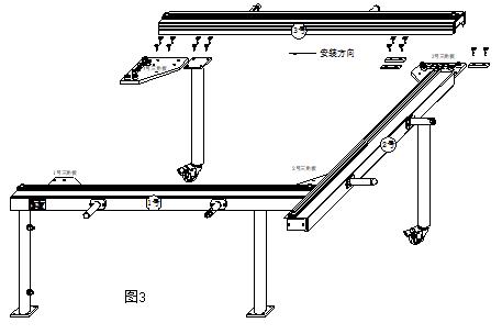
3. The third step, as shown in Figure 3: Install the No. 3 beam, the No. 4 moving foot and the No. 4 triangle plate (the assembly method is the same as the No. 2 beam)
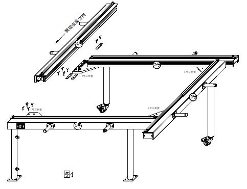
4. The fourth step, as shown in Figure 4: connect the No. 4 beam with the No. 1 triangular plate and the No. 4 triangular plate;
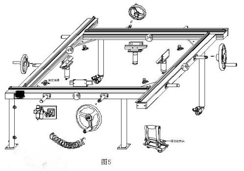
5. The fifth step, as shown in Figure 5: After the No. 1-4 main beam and the 4 machine feet are assembled, start to assemble the cylinders. It is fixed on the outside of the triangle plate connecting the 1st and 4th beams, and the three sets of two-way joint components are fixed on the remaining three triangle plates in turn.
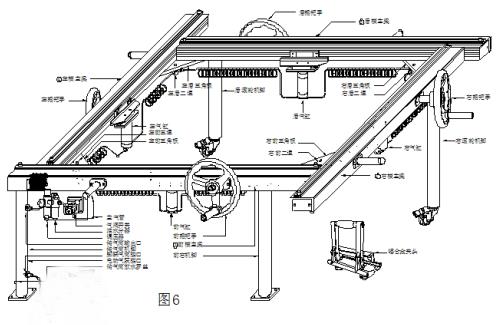
6. When installing the gas pipe, please look at the assembly parts (as shown in Figure 6).
1) The outer side of the lower part of the air tank machine foot is the foot air pump connector (the connector is a one-way valve connector), the inner side of the lower part is the electric air pump connector, and the upper connector is the air tank outlet connector.
2) The air outlet of the air storage cylinder is connected to the left joint of the oil-water separator, (the right air outlet of the oil-water separator is connected to the left air joint of the air valve switch).
3) The air outlet at the lower part of the air valve switch is connected to the tee on the left side of the No. 1 beam, and the air pipe is connected in sequence (the tee to the cylinder to the two-way joint).
7. Install a cover at the end of the main beam, and install the handle on the rotating shaft outside the side of the main beam, so that the main shaft of the handle can be rotated to adjust the tightening screw.
8. There must be 4 ball bearings on each Mesh clip of the main beam, and the baffle at the end of the installation should use rubber buffer pads and M4*10 nipple head screws.
9. In order to improve the firmness of the machine, the first two supporting feet of No. 1 should be tightened to the ground; the main beams of No. 2-4 should be able to move relatively easily. To readjust and check the angle of the main beam, tighten the fixing screws to ensure that the handle can rotate freely, check the sealing condition of the air pipe joint and the cylinder, and there must be no air leakage, otherwise the air pressure system of the screen frame will not work properly.
10. Whether the machine is in a horizontal position before stretching the net, whether all the components are installed, and the speed of the air pressure can be controlled by the throttle valve. The first time the net is stretched is also a check on the function of the machine.
